Thursday, August 29, 2013


There are times that take a lot of the fun out of running a shop, and this 2004 Dodge Neon is a good example of that.  About four months ago the car showed up and it was setting a P0344 for a camshaft sensor signal sync error. The scan data at that time showed the camshaft signal missing, and measuring the signal in between the sensor and the PCM confirmed that it was inoperative because of the presence of the five volt reference that comes from the PCM that the sensor pulls to ground when it turns on. The sensor is a Hall Effect design that turns on when a magnet that is attached to the back of the camshaft passes close to it.  The last two checks for the power to the sensor and the ground circuit showed that the power and ground were correct so replacement of the sensor and it’s pigtail connector was indicated. The repair was completed, the code cleared and the vehicle was road tested with no other troubles found.

Monday afternoon the customer calls and reports the same symptoms of surging over 2100rpm and the check engine light is on again. We told him to bring it right down and when he showed up it was working just fine again. Pulling the code the P0344 was set in the history and scan data showed “cam lost last”. At this point there wasn’t much else to do but run the customer home and set up my testing connections to prove where the fault was occurring at.  The car ran fine the whole way to his home and back down to the shop. Leaving it run in the shop with my wife paying attention to it, the circuit failed at some point because the light was on and scan data showed sync  lost, but the signal was fine on the oscilloscope.

Several start and run routines were then performed over the next day and no trouble was identified. When attempting to diagnose a problem like this the only thing that really works consistently when trying to solve them is a good plan and a lot of patience. Many would resort to throwing a camshaft sensor at it and ship it out the door, and of course there is a chance they might be successful. The problem with that approach goes hand in hand with something the customer said during this phase of the testing. He was already losing confidence in the car and started lamenting the idea of replacing it. If a tech guesses and gets it right, the symptom may go away but the customer really has no reason to believe that the car is really repaired and it could act up on him at any time and then he would fear being stranded. The only way to restore his confidence in the vehicle is to be certain that the problem is found. Since leaving it run in the shop wasn’t giving me the information that I needed, the next step is to go on a suicide mission and drive the car and diagnose it when-ever and where-ever the problem occurs. So with the scan tool and the PICO four channel scope connected to the critical circuits it was time to hit the road and hope it acts up.

As luck would have it it didn’t take long to occur, but it did it on one of the worst hills in the area to have a car that wasn’t running right. This hill is about a half a mile long and about four hundred feet high with a blind curve in the middle of it, and there was a few moments this really seemed like it might be more than just a cliché as a suicide mission . Here is a screen shot of the camshaft and crankshaft signals while the problem was occurring.


The advantage of having both of those signals at the same time is that they share their powers and grounds which are both provided by the PCM. With the crankshaft sensor signal operating normally, and the five volt reference from the PCM to the camshaft sensor visible, the problem had to be in between the scope connections and the camshaft sensor. Here is a capture taken while the signals were both operating normally for a comparison.


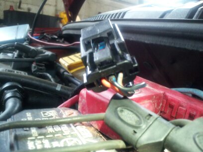
Armed with this perspective closer examination of the harness and the connector was in order. The camshaft sensor connector isn’t very easy to reach in the car even though its right on the back of the head. (drivers side of the car).  One of the tricks is to grab the harness with a hook tool and start pushing and pulling on it to try and get the signal to drop out. That wasn’t successful, but when I put the tool right on the connector for the camshaft sensor I could push downward and the signal went open, and pull the connector back up towards the sensor and it would start working again.

Here is an important capture that reveals the circuit fault. Can you tell what part of the circuit is failing?


Well that’s great, the car has a new sensor and pigtail that were replaced just four months ago and there is clearly something wrong with one of them. So now it was time to shut the engine down, unplug the connector and pull it up where I could see it and this is what I noticed.


If you didn't see it in the first picture, how about this one?


 Here is another view.


Looking from the connection side you can see that the middle pin is pushed part way out of the connector. Grabbing the wire with a pair of needle nose pliers I could push the pin all the way into place, and then pull it right back out. Great, the new pigtail has a damaged pin, or pin retainer.


Taking the connector apart I could see the plastic retainer was damaged, and looking at the pin closely the terminal space was way too small for the camshaft sensor pin to fit inside. The problem was that the pin was originally flawed, and instead of making a good connection to the sensor, it pushed out of position and for the last few months and a couple thousand miles was simply just
touching the middle pin of the camshaft sensor. With the problem confirmed the easiest thing to do was to repair and then secure the pin in place inside the connector.

The vehicle was put back together and road tested again with no more troubles found. We called the customer to let him know what we found and how we fixed it.  When the customer came to pick up his car he wanted to know how much he owed, and well the answer to that was nothing of course, this is how we provide a warranty for our customers. From our point of view this shouldn’t have happened so it’s up to us to make it right if and when anything like this ever does occur. All told some two hours of labor time are gone over a pin that probably cost a penny for some machine to make a hundred of them. We take it on the chin for our customers and in the end all that’s really important is that we stood behind the work that we did and the materials that we sold. Hopefully our customers recognize that it’s how we handle the problems that are as much the measure of our shop as are our successes the first time around. Even so, it’s an easy choice to do the right thing, but that doesn’t make it a very fun thing to do.

Monday, August 26, 2013

2010 Escape AC not cold. Edited version to explain the theory better.


Those pressures should look a little confusing, but they tell quite a story about the condition of the AC system in my Escape and why it isn’t cooling. The static pressures should closely match ambient temperature when everything has gotten to sit and cool off so that it’s somewhere between 60f and 85f. If the under hood temperatures are high than that will push the refrigerant pressures higher as well. But that high side pressure is too high, in fact after sitting for only a few minutes the two sides should have equalized, yet this sat for about an hour and the pressures were almost 100 PSI different.

One test that needed to be run is use a refrigerant identifier, this should be done on every job because you never know what has happened to a system prior to you looking at it. When the system is fully charged some of the refrigerant in it will be in a gaseous state and some of it will be liquid. When the compressor is running, the pressurization of the refrigerant concentrates the heat that it possesses on the high side , and that allows the condenser to dissipate that heat and allow the refrigerant to condense into a liquid.  By taking advantage of the latent heat of vaporization, the refrigerant actually releases more heat than just the pressure change would suggest. From there the refrigerant travels to the expansion valve or orifice tube. As the refrigerant passes through the orifice tube or expansion valve  the drop in pressure causes the liquid to boil and it absorbs heat from the air passing over the evaporator as it turns into a vapor.

There are a lot of things that can contaminate the refrigerant don’t condense into a liquid under the pressures and temperatures that an automotive AC system operates and the result lf them being in the system is typically higher than expected pressures, and very poor cooling. With my Escape  the static pressures are high, but that’s a function of the under hood temperature.
The next thing to do was to start the engine and see what the system did. The high side stayed at 210 psi, while the low side pressure dropped to 30psi and stayed there. Those would be normal pressures except the evaporator outlet tube  temperature was 78f, and that’s way too high.  That surface temperature means that there was no liquid refrigerant left to evaporate and absorb heat. Most techs would expect that with a high side of 210psi , and a low side of 30psi the system should be nice and cold, so why wasn’t it? Is this related to the high side static pressure being much higher than the low side at rest?

The answer to this one is that the expansion valve is sticking, or plugged up with debris sealing it off and reducing, if not completely blocking refrigerant flow. Now if you thinking about this, shouldn’t the compressor pump all of the refrigerant to the high side and pull the low side into a vacuum? It would except for the fact that it’s a variable displacement compressor that regulates the low side at 30PSI, so it simply stops pumping when the low side pressure reaches that pressure. The repair will include a new expansion valve and a receiver drier assembly. I’ll upload some pics of the repair if possible over the next couple of days.   

Be an AC Pro

You've seen the advertisement. AC not cold enough, just buy a can of refrigerant and dump it in and you are a hero, right?

This is my car, and it has not had any refrigerant added to it. The AC has worked fine up until early last week. Then I noticed while we were on the road, the AC was cold, then not cold, then cold again. The impression was that it was low on refrigerant and the clutch was being commanded off.  On Saturday I knew that I was going to have a chance to look at it so I pulled it inside after a quick run to Subway for lunch. It was about an hour later when I got to attach the gages and this is what I found.


The engine was not running, this is the static pressure after the car had been sitting for about an hour.

OK, what does this mean and what is your next move?

Tuesday, August 20, 2013

The Taurus no-start at that point was a theft deterrent issue and the code description was that the key that was being used wasn't learned. This happens when someone gets a new key that the vehicle hasn't been trained to recognize, and it can occasionally occur if a key gets damaged and sends an incorrect response. This can also happen if someone replaces the module that has the PATS function supported in it. What we needed now was another key to see how the vehicle reacted. With the IDS (Ford factory scan tool) we can access the PATS system and train the vehicle to accept the new key. This can also be done with a J2534 tool and a short term subscription to Ford's website. One other thing that had to be done before calling the customer was check to see if the function for a consumer to add a new key was enabled and it was.

I called the customer and explained what we had found and right away she told me that she had a "dummy" key made that was only for opening the doors or trunk. I asked her where that key was and she went over to her desk and said that she got it out and it was in her hand. I then asked what key does she usually use to start the car and she told me that the one that I had was the usual key. Then I asked how many keys does she have in total and she said three.

Hmmmm.

Then the conversation got a little confused as she mentioned that a relative was involved with doing something with the car when it acted up. At that point I asked her if she could come to the shop and bring me the other two keys.

When she got to the shop I took the key that she had provided and showed her that when I tried to start the car it didn't start and showed her that the theft light was flashing. Then I took one of her other keys and tried to start the car and the theft light was still flashing. That's normal for the car to do that because once it sets a theft code it goes into an anti-scan mode and there is a thirty second to two minute wait before it will identify another key. About forty seconds after the key was installed the lamp stopped flashing, I turned the key and the car started.

She told me that was the key that she got out of her desk and maybe one of her relatives had put the wrong one back by mistake. So I tried the other key that she had brought and of course the car started. At that point there was one thing left to do. I turned the car off and waited a few seconds. Then I turned the key to run for three seconds and then turned it off. I did that with the second key that worked. Then I repeated that with the key that she had given us when the car was towed in which allows the car to learn that key. That's why checking to see if the customers key learn function was enabled. Now she had three keys all trained to the vehicle and no more dummy key.

The last thing we did was talk about keeping her battery charged, she told me that since her visit a couple months earlier she did get herself a battery charger but had only used it once. Now she knows she needs to do it about once a week.

Monday, August 19, 2013

When we got to the shop Friday morning there was a white 2002 Taurus sitting there that had been towed in the night before. There is some history on this car, it's typically been worked on by a family friend and about two months ago was towed into our shop after several failed attempts to solve a no-start had to jump the car to start complaint. That turned out to be a combination of issues which included a battery that developed a high rate of self discharge and that was brought about by the owners typical use where she doesn't drive the car long enough each time she starts the car to fully recharge the battery. To maintain a strong battery an average trip should be around five miles with no accessories and could easily be more than ten miles during conditions when a lot of electrical power is being used. (aka headlights, defrosters, wipers, etcetera) The customers average trip is under two miles and only on rare occasions drives five to ten miles. That kind of use over time depletes the batteries reserve capacity and has it operating under a condition of a low state of charge and that leads to sulfation and battery failure. There was a note that said the car would not start, would not crank. The family friend had already replaced the alternator even though it tested OK at the parts store, and had removed and then re-installed the starter after it was tested and shown to be OK. The parts store said that the car needed a new battery.

Think about how you would approach this car and begin your diagnostics. The answer and findings will be in the post just below.
I went out to start my testing and the first step is simply to see what the car does, or essentially verify the reported problem of the car not cranking. When I turned the key to the run position the dash lights all bulb checked, and when I continued turning it to the start position there was no sound at all. The car did not crank, and there were no sounds from any relays being commanded on or off.

Now pause for a moment before reading further what should you do at this point?

The answer is look at all of the lights bulb checking on the dash, go ahead and even turn the key off and back on if you have to in order to see all of them. Some of the critical lamps you want to see are the charging system indictor if used, without the engine running it should be illuminated. You need to see the check engine light, it also should be on. Keep in mind of you leave the key on for ten or more seconds without cranking the engine some cars may flash the check engine light and on some it will go out. We will leave the explanations of why they do that for another day, but if you don't see it simply turn the key off for about five seconds and turn it back on and it should be on again.

During this step I noticed a lamp flashing on the dash, it was low on the right hand side of the cluster and it displayed the word "Theft". Now that's a clue as to why this won't start. It's time to grab the scan tool and my battery tester and see what's happening. Now why the battery tester? If you don't have good system voltage all bets are off as far as how a vehicle will operate. The batteries open circuit voltage was low at 12.1v but passed at 94% health. It needs charged but it doesn't need replaced like the parts store told her. With the scan tool I retrieved a B1601, ignition key not learned or faulty signal from the key.

What's the next step? I'll post the answer in a day or two.

Friday, August 16, 2013

Toyota Tacoma O2 sensor puzzle

2006 Toyota Tacoma had an engine put in it and then it started setting codes for lean exhaust, and after replacement of the O2's and air/fuel sensors it finally settled into setting P0138, and P0158. One is B1S2 voltage high and B2S2 voltage low. Bank #1 downstream sensor voltage was going to .1v or lower and staying there, while the bank #2 downstream sensor would go to .8 and stay there. Bank 1 A/F sensor voltage was 3.1v, indicating rich,. and bank #2 A/F sensor 3.45 volts indicating lean.

Now before I say what was wrong, see if you can figure it out or what could you do try and prove what was wrong with the truck.

FWIW fuel trims were adding fuel to bank #2, and taking fuel away from bank #1

Think this through before reading the answer below.

Toyota Tacoma Puzzle Answer

If you take note of the highlights and make comparisons you would see that B1S1 (bank one, sensor one, upstream) shows rich, while B1S2 the downstream sensor on the same bank shows that its lean. There are a couple reasons that could cause that to occur, one would be an exhaust leak between the sensors and checking for that none was found.

Let's look at the other bank now. B2S1 is showing that it's lean, while B2S2 is showing that it's rich. Now unless there is a sensor or circuit issue that really doesn't make any sense.

So how could we rule out a sensor issue from the front seat of the car? A hard acceleration drives the system rich, and both upstream and downstream sensors reported the condition correctly. A closed throttle decel then results in a fuel cut-off or extremely lean and all of the sensors reported that correctly as well. So at that point one or more could still be innacurate, but they are definitely working for the most part. (Rich has the upstream sensor voltage dropping to 2.4v while the downstream sensor reports .8v or more, lean the upstream sensor goes to 4.99 and the downstream drops to .1v)

We find bank to bank fuel trim issues from time to time, but fully expect to see both sensors on either side reporting the same condition and the fuel trim data showing that the PCM is trying to correct for it. The data seen in the fuel trims was really confusing, while it appeared to be making corrections, it was going the wrong direction according to the upstream sensors. Bank #1 was rich and fuel trim was adding fuel instead of taking it away, bank #2 was lean and the fuel trims was taking fuel away.

This truck was demonstrating a condition that proves the downstream O2 sensors have more authority than the upstream air/fuel or O2 sensors have. Combine that with bank #2 downstream sensor reporting more fuel than the upstream sensor was reporting and the only thing that makes sense is someone has cross connected the down stream sensors sometime in the past. They even secured the harnesses in place on the brackets on the transmission just like they are supposed to be making it difficult to notice visually.

We stopped in a parking lot and disconnected the downstream sensors, released the harness from the brackets and re-routed them across the top of the transmission to the opposite sides and re-connected them and then road tested again. Now the downstream sensors were on the correct sides and the system functioned correctly. The troubling part there is the shop that originally put the engine in didn't have anything to do with that part of the wiring harness that was above the transmission, they didn't cause the problem. But both they and the second shop made the same mistake, they "assumed" the that problem was related to the engine replacement instead of just troubleshooting it. By starting with that assumption in place they were blinded to all the possible causes and got trapped. Between them they each had fought this for a week, and with a disciplined approach it was diagnosed and corrected in about a half an hour.

Now for the kicker, the codes would set as pending within a few minutes of driving, and if you shut the engine down and then restarted the truck would light the MIL (check engine light) in a few minutes after that. That pending code and subsequent MIL would prevent many of the other tests the computer has to run from being performed. That means the truck could easily still have other issues that can cause the MIL to come on, but there is no way to know until the computer gets to run the tests and that of course explains why a tech can do a good repair only to have the light come back on a few days or a week later and it really is a different problem even though to a customer the light coming back on looks like "its doing the same thing".

Tuesday, August 13, 2013

 2002 Acura RSX 2.0l

The customer reported that the car starts, runs for a few seconds and then shuts off. The Check Engine light is on. Pulling codes revealed a P0341 CMP/CKP (camshaft/crankshaft) synchronization error. The computer constantly looks at the camshaft sensor waveforms, and compares them to the crankshaft sensor wave form to make sure that the camshafts are in time. In the event of a mechanical failure and the waveforms get out of sync, the computer shuts the engine down to try and prevent further damage. The customer reported that several people have already looked at this, including removing the valve cover to inspect the timing ,marks and failed to find the cause of the problem.

Since the car runs for a few moments that's plenty of time to get a compression waveform.


The cursors mark the two compression peaks, so between them is all four strokes of the engine starting with decompression, then the exhaust, intake, and the next compression stroke. By measuring the time in between the cursors, you can divide by four and then mark the individual strokes of the engine and see if the camshaft is in time or not.


The total time between the cursors was 99.2ms, divided by 4, that's just about 24.9ms, so the one cursor gets moved to first display the decompression stroke which is when the crankshaft turns from TDC (top dead center) to BDC (bottom dead center) and then the second one gets moved to show the exhaust stroke as the crankshaft turns back to TDC.


See the rise in pressure at the end of the exhaust stroke? That means the cylinder pressure was rising when the exhaust valve should have still been open during the overlap of the intake valves and exhaust valves. You can see the pressure start to drop just before TDC, that's the intake valve opening.

So when did the exhaust valve open, and how far out of time is the exhaust camshaft?


The waveform is created by two full revolutions of the crankshaft, so that's 720 degrees of rotation that took place in 99 ms. Dividing 720 by 99  gives us just over seven degrees of rotation per ms.


The point where the waveform stops dropping on the decompression stroke shows us when the exhaust valve opens. By placing a cursor at that point, and multiplying the time elapsed from TDC you can see that the exhaust valve opened up about 56 degrees after TDC, that's about 90 degrees early! That also explains why the exhaust valve closes to soon.

So it's confirmed that no matter what we see with the timing marks when we get this apart, the camshaft is out of time, and the computer is correct in setting the P0341.

Questions?

Friday, August 9, 2013


It’s nice to get an easy one once in a while amid all of the random failures that we usually have to fight through. But even an easy one, or should I say easier one demands both attention to detail and discipline to make sure that you haven’t missed anything significant in the early stages of the diagnostic routine.

Another shop brought us a 2001 Chevrolet Impala with a 3.8l engine, they reported that they had replaced the ignition switch but the car still wouldn’t start. Well, yea that car uses the pass lock anti-theft system, so when the ignition switch and lock cylinder are replaced, the system doesn’t recognize the voltage signal from the new pass lock sensor and the BCM reacts as if there is a theft being attempted. Attaching a scan tool and accessing the BCM codes there was a B2960 found for the passlock sensor signal valid but incorrect. That’s an easy fix and the system can be retrained with a re-flash routine in about ten minutes, or it can also be done with three ten minute key-crank-on cycles.

The rest of the story on this car was it was abandoned and impounded so it hadn’t run in a couple of years, which is why they had to replace the lock cylinder and key. Once the pass lock system was retrained the car was now able to crank and it fired but it stalled right away. With practice a technician can hear the way an engine tries to start and how it dies and actually recognize if a problem is specific to one or more cylinders, he/she can often tell of the car is too rich or too lean and if it lost spark or fuel to all of the cylinders. This one sounded rich, and it appeared to not be losing spark. Rich often allows for one or two cylinders to fire while cranking but it’s random, and opening the throttle normally allows more air in than the engine is getting fuel and the engine then clears up and starts running. The problem was this one wouldn’t clear out, in fact it would seem like it briefly cleared out and then got worse and would even kick back against the starter. At this point it seemed that I might just be discovering why someone walked away from this. Since the tech II was hooked up it made sense to check the essential scan data. Both the intake air temperature sensor signal and the coolant sensor signals reflected the ambient temperature of eighty degrees, the map sensor showed ninety-seven kilopascals which is close enough to normal ambient pressure, the cam and crank rpm signals matched when the engine was trying to start but the MAF sensor was jumping to thirty-five, then fifty- eight and up to seventy-six grams of air per second when it would stall and the engine just barely to one thousand rpm.  So that was clearly wrong, the sensor was way over reporting, but even then the engine just didn’t react to the throttle the way it should be expected to. Fortunately with the MAP sensor in the system, the MAF can be disconnected and then see how the system reacts. By disconnecting the MAF the engine now would start and idle, but it would not rev up when opening the throttle, in fact it sounded very labored. Looking at the MAP signal it was reporting about eighty kilopascals. That meant there was very little vacuum being generated, opening the throttle even the slightest amount had the MAP reading showing the same ninety-seven  kilopascals that was seen before cranking the engine.

One other important note was the fuel trims were taking away about twenty five percent of the fuel pulse. That meant that the computer was at least trying to compensate for the system being too rich. When you have a speed density system, which is what this became with the MAF disconnected the computer looks at the high manifold pressure as an engine that is working real hard to accelerate, so it calculates a long pulse width. But in this the airflow to match really wasn’t there so that ends up being too much fuel and the trims have to react. At this point there really was only two possibilities for the condition, either the exhaust was restricted or the camshaft in the engine is out of time with the crankshaft. Fortunately one simple test can provide the answer to which one it is and that’s do a running compression test with a pressure transducer and measure the valve opening events.

The first capture is cylinder number three running with only cursors measuring the entire cycle. That allows the time elapsed between the compression peaks to be measured, and then divided by four to give each piston stroke.

The second capture shows cursors set for the exhaust stroke, the pressure in the cylinder should go below atmospheric pressure before the piston gets to the bottom of what would normally be the power stroke of the engine, then the exhaust valve open at just about forty degrees before bottom dead center and since the cylinder is in a vacuum, the pressure rises because the exhaust is at, or slightly above atmospheric pressure. This second capture proves that the camshaft is in time.
 

Now all we need to do is speed the engine up. Notice how you no longer see the compression peaks, they are clear off the top of the screen, at the same time the exhaust stroke plateau has risen as well. The horizontal cursor allows that pressure peak to be measured and its over forty psi. That’s way too much back pressure and explains why the car won’t run above an idle.


At this point the discovered repairs need to be performed before any more diagnostics could be performed. There may easily be other issues that require attention, but sometimes you don’t have any choice because problems like these two will make proving anything else almost impossible IMO.

Saturday, August 3, 2013

Hyundai Sonata Transmission 2

 Here are the current waveforms for the Hyundai Sonata that prove that the circuit is good to the  internal power splice for the overdrive and second gear solenoids, and the failure is between that point and the harness pin at the transaxle connector for the overdrive solenoid ground control. (yellow/white)  At the same time, these captures also prove that the circuit is going open and not grounding. This first capture is normal operation. The red trace is from a current probe that is attached to the common power input for the solenoids. The green trace is the overdrive solenoid circuit that is randomly failing. The tan is the second gear solenoid command and the blue is the overdrive solenoid.
 One of the first things you should notice are the three rises in current on the red trace. There are three solenoids that are actually powered up by that supply, so you see the PCM confirming all three solenoid circuits. Look at the duty cycles displayed on the tan and blue traces. If you were looking at those circuits with a volt meter, it would average that and display about six volts which is what the transmission shop saw. Notice how the PCM stops pulsing the solenoids and pulls them to ground?  You can see the corresponding rise in current when that occurs in the red trace. Now notice how the current rise on the green trace lines up with the grounding of the overdrive solenoid on the blue trace?
These are the key elements that we need to pay attention to when a failure occurs.

So here in the next captures are the circuit failure. I've already mentioned that the circuit is going open, or you could look at it as very high resistance. Try and figure out what you see in these and we can discuss them a little later.